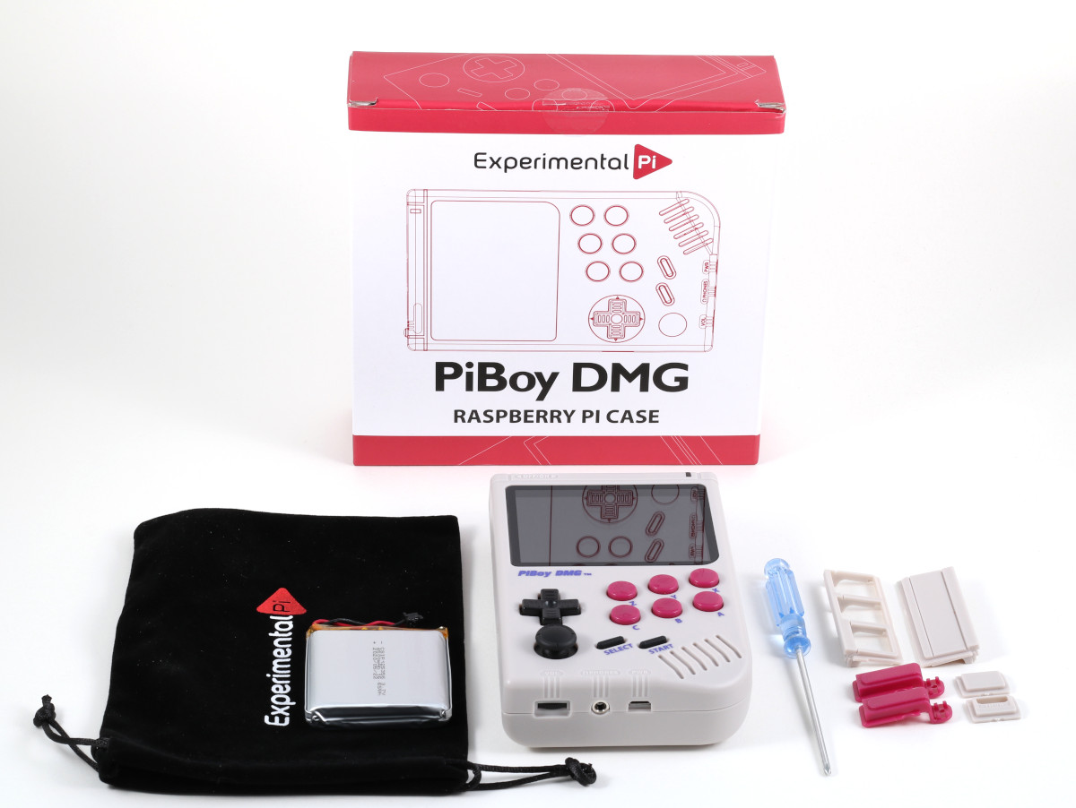
Figure 1: The PiBoy DMG Kit.
Thank you for purchasing a PiBoy DMG kit. Below are instruction on how to assemble the kit.
1. Remove the back of the PiBoy case by removing the six screws holding it in place. The provided screwdriver fits the screws holding the case together. Place the front half of the PiBoy DMG case screen side down.
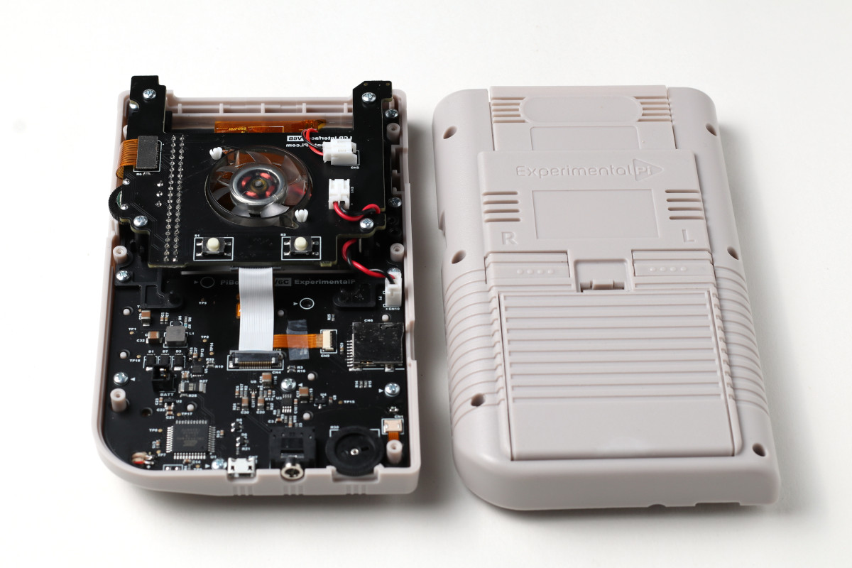
Figure 2: The PiBoy DMG case back removed.
2. Unscrew the fan board and lift it out of the way.
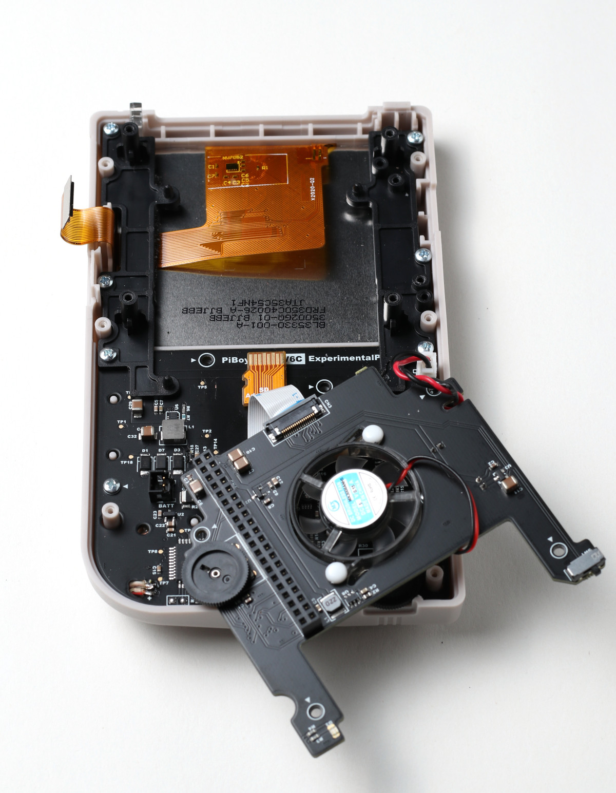
Figure 3: The fan board removed and lifted away for the installation of the Pi board.
3. Place the faceplate for the Pi model being installed on the proper end of the Pi. Test fit the faceplate with the Pi before installation to ensure the proper one is being used.
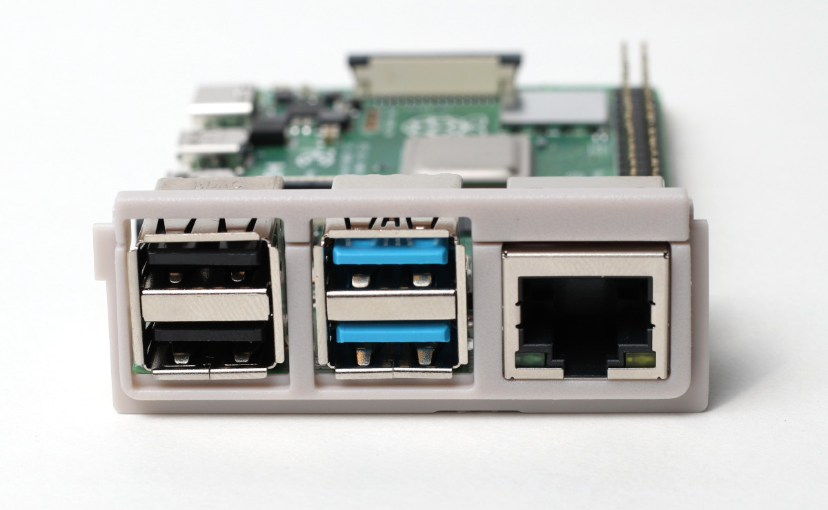
Figure 4: The faceplate for the Pi installed on the Pi.
4. Lower the Pi in to the case so that the end of the SD card cable sticking up slides in to the Pi’s SD card slot. Use your fingers to make sure the cable is fully inserted in the slot. Once the cable is all the way in the slot, set the Pi down on the 4 nubs that correspond to the hole’s in the Pi board.
Do not use tweezers to manipulate the SD card cable.
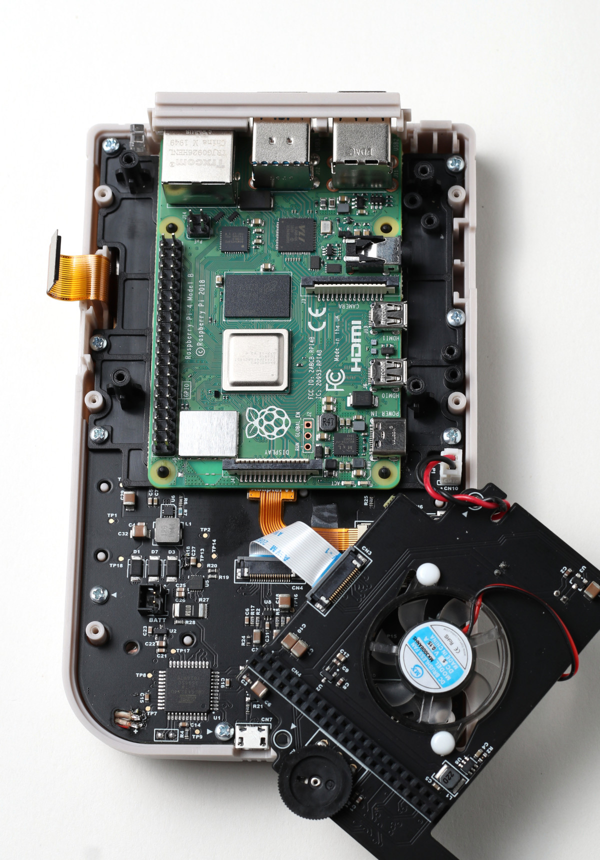
Figure 5: The sd cable inserted in the Pi and the Pi installed in the case.
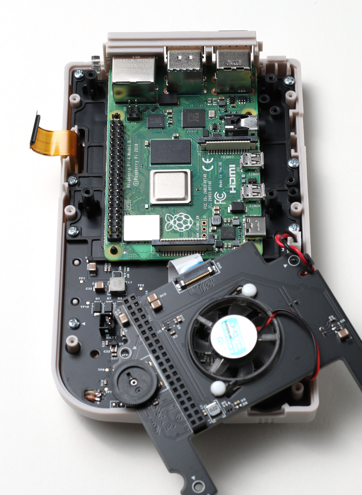
Figure 6: The Pi placed on it’s standoffs.
5. If no HDMI adapter is being installed place the blank plate in the opening on the right side of the case. If an HDMI adapter is being installed connect it to the Pi’s HDMI port so that the other end of the adapter is in the opening for the case. Attach the proper faceplate to the end of the connector.
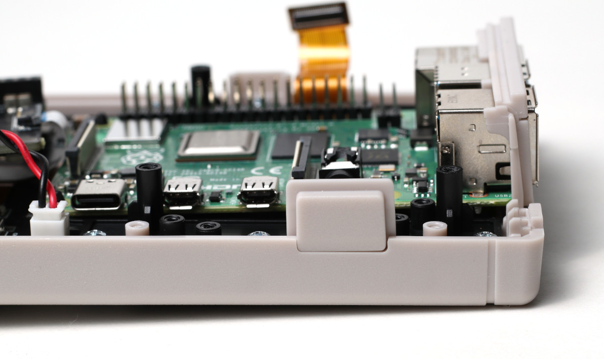
Figure 7: The HDMI adapter plate installed if not HDMI adapter is installed.
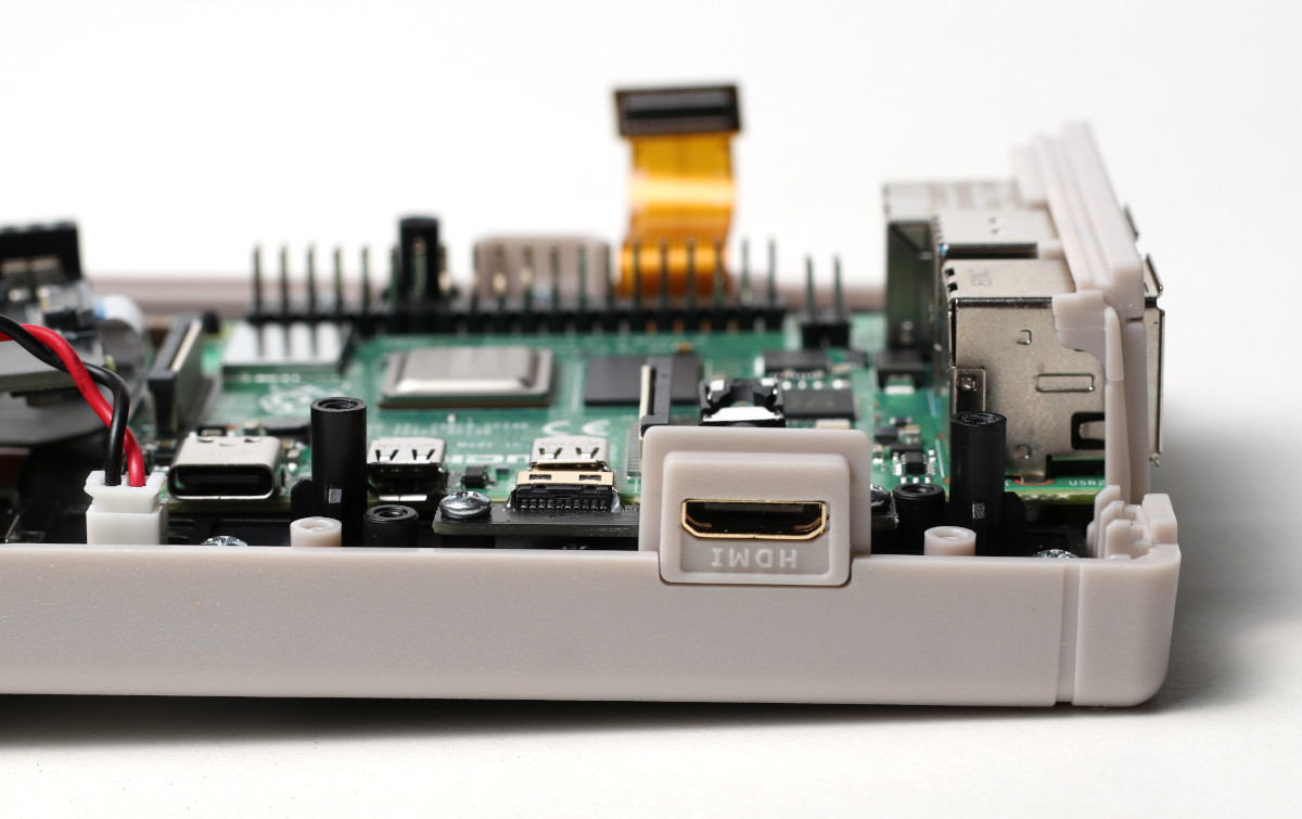
Figure 8: The HDMI adapter plate for the HDMI adapter.
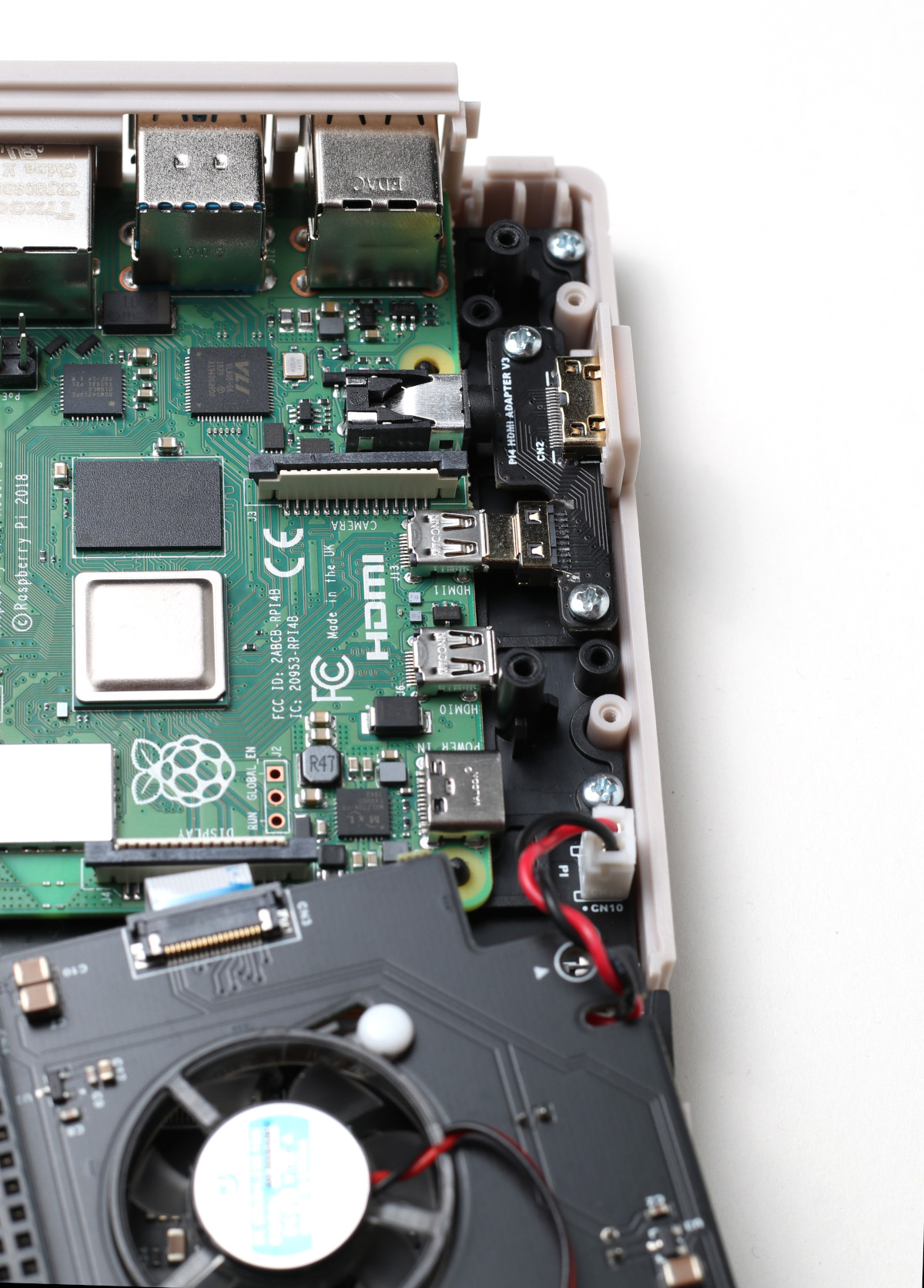
Figure 9: The HDMI adapter installed in the PiBoy DMG.
6. Place the fan board back over the Pi. The fan board will line up with the standoffs for the Pi. Push down on the board to connect the board to the header pins on the Pi. While seating the board make sure the plastic LED indicator stays aligned. Makes sure the board is fully seated.
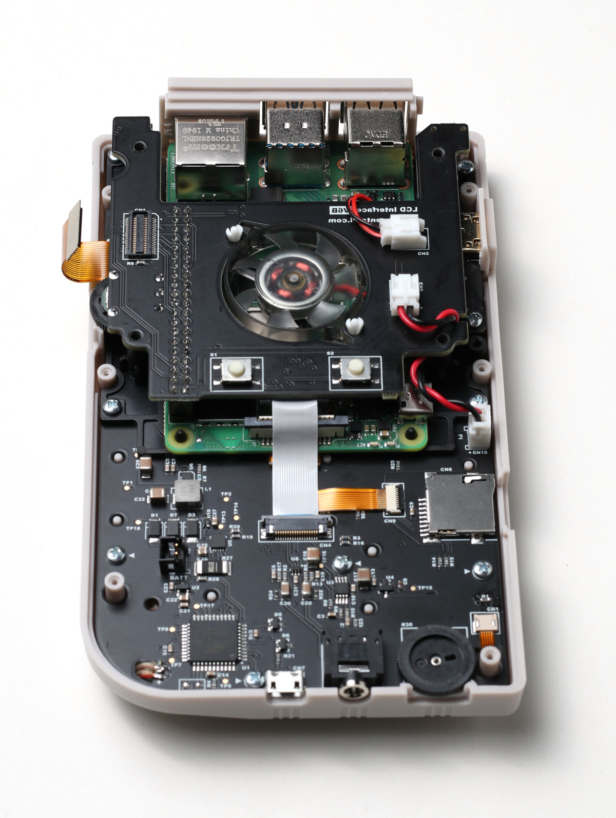
Figure 10: The fan board installed on top of the Pi.
7. Using the screws removed from the fan board earlier, screw the fan board in place.
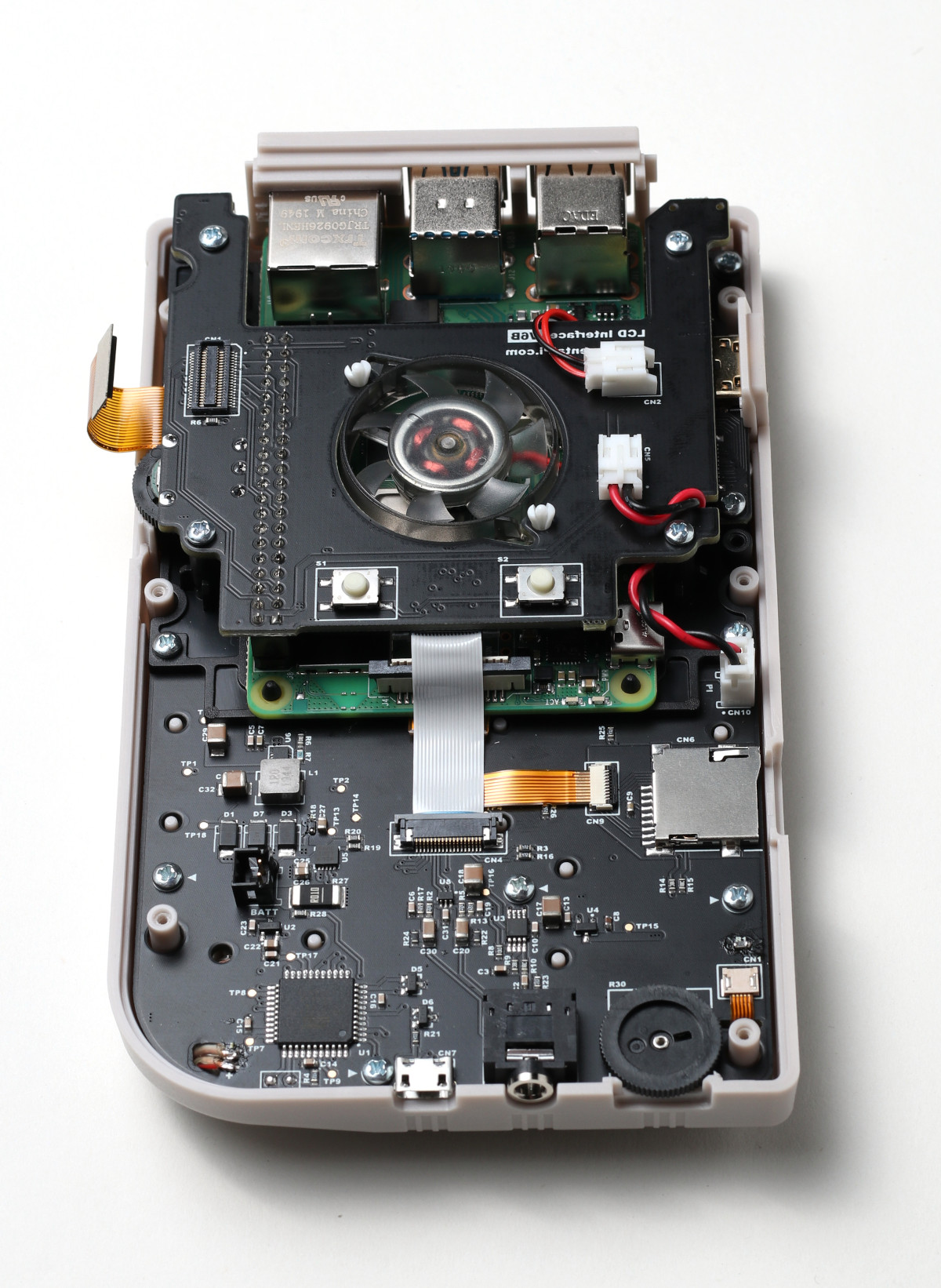
Figure 11: The fan board screwed in to place.
8. Connect the flex cable for the IPS display to the header located on the fan board. Line it up squarely and gently press down on it. You should feel a solid click once it’s seated.
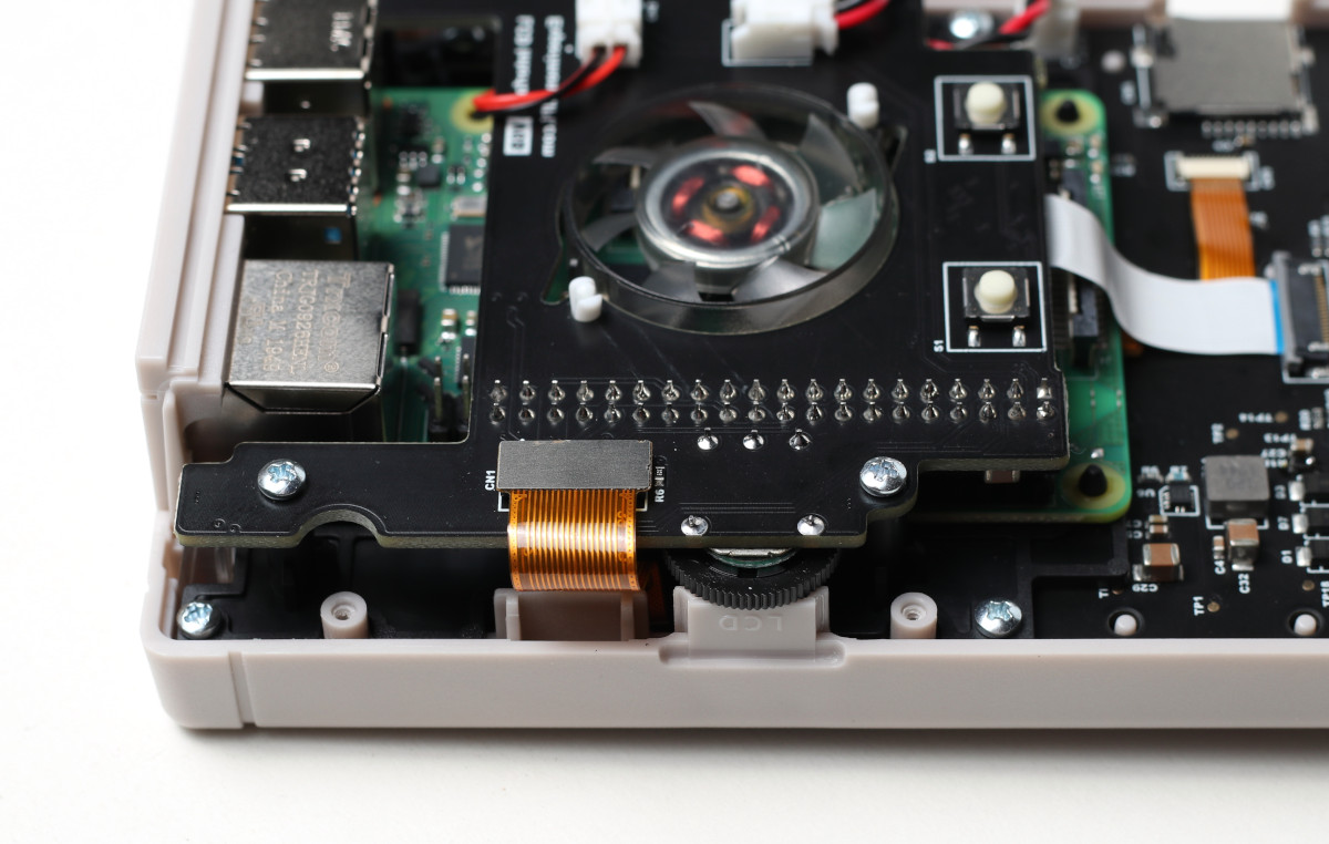
Figure 12: The IPS screen cable connected to the header.
9. Locate the plastic power switch in the bag of parts. It is connected to the switch in the upper right hand side of the fan board and will fit loosely. There is a ” T” shape on the switch. Install it with the “T” shape upside down.
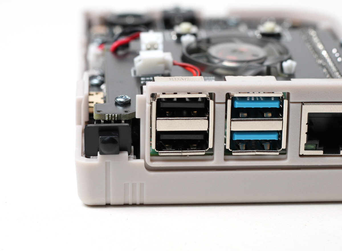
Figure 13: The power switch installed.
10. Place the back of the PiBoy case on. While installing it the power switch and faceplates will have to be kept aligned to make sure everything slips in to place correctly. Use the 6 screws previously removed to fasten the case back in place.
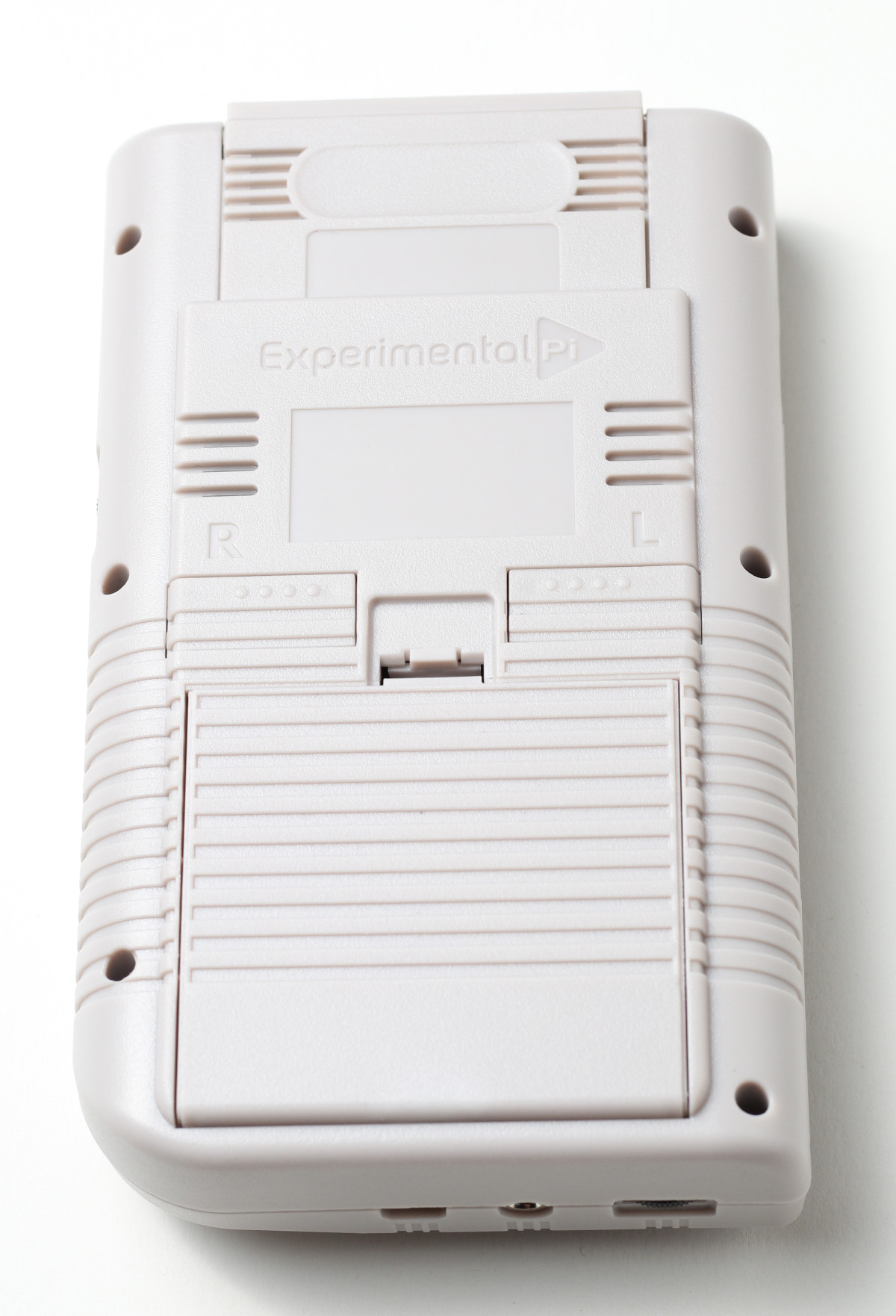
Figure 14: The back of the PiBoy case installed.
11. Remove the battery from it’s packaging and note the black and red wires attached to it. Remove the cover for the battery compartment and connect the battery to the header in the compartment. The battery connector will only go in one way. There are markings inside the case that show positive (+) and negative (-). The side of the connector attached to the red battery wire corresponds with the (+) marking in the compartment.
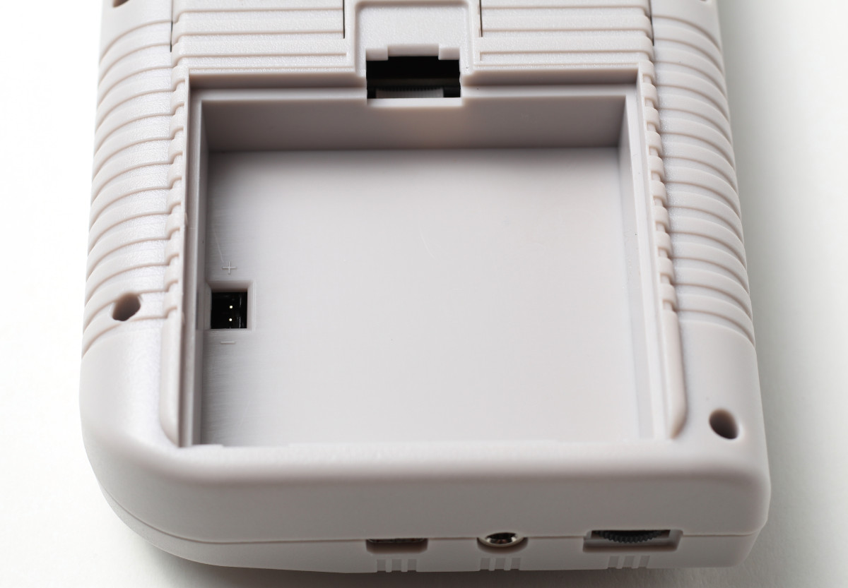
Figure 15: The battery compartment of the PiBoy DMG. Note the markings for battery polarity
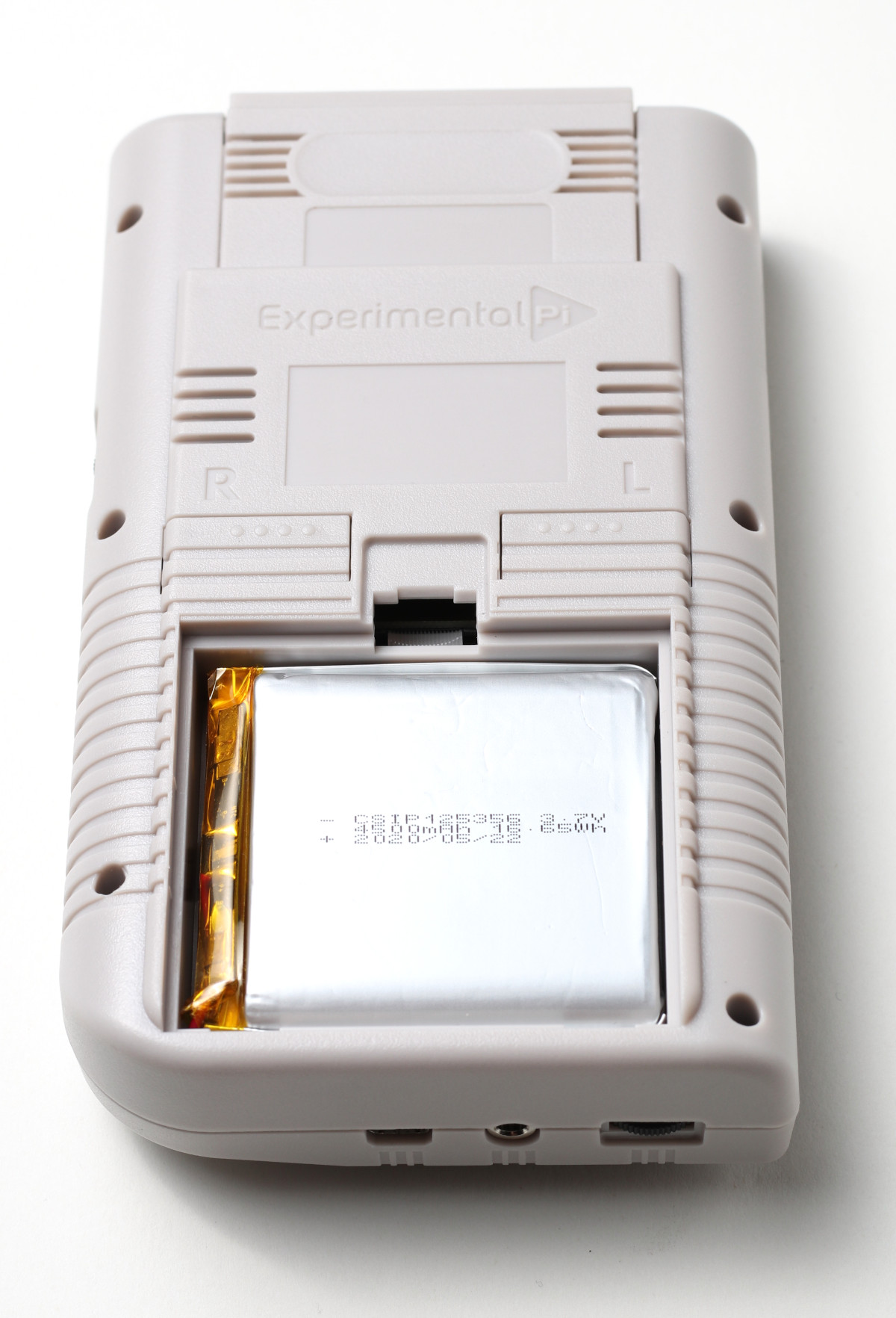
Figure 16: The battery installed.
Please see
this article for instructions on setting up the software side of the PiBoy DMG.
