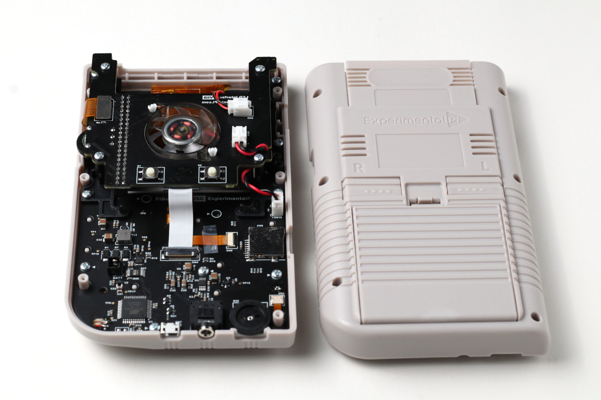
Figure 1: The complete internals of the PiBoy DMG.
This article covers the major internal parts of the PiBoy. A description and image of each part can be found below.
Gold SD Ribbon Cable
The gold colored ribbon cable connects the SD card socket of the Raspberry Pi to the SD card header on the control board. If either is not seated properly the PiBoy will have a problem booting from the SD card.
Shown below is the flipped style SD ribbon cable, some models may have a different SD ribbon cable and header. On some models the header will face the opposite direction, and the cable will insert directly into the header and lay flat. On all models, it is important not to crease the ribbon cable.
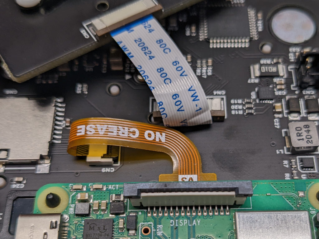
Figure 2: The gold colored flipped style SD cable.
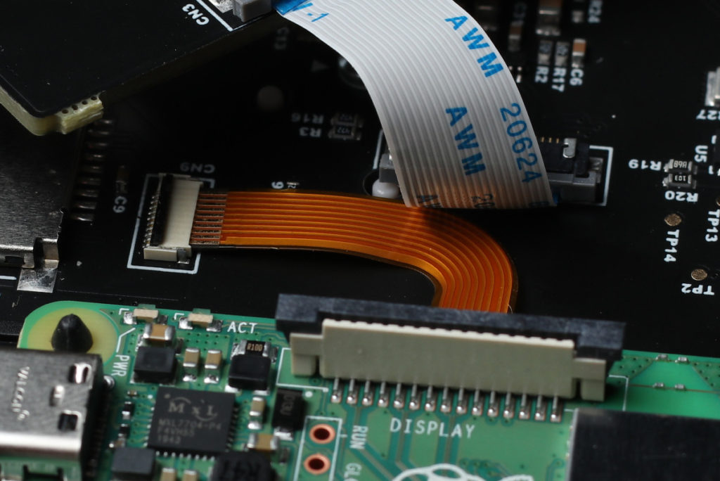
Figure 3: The gold colored flat style SD cable.
White Ribbon Cable
The white ribbon cable connects the control board to the Raspberry Pi and allows communication between the control board and the Raspberry Pi. The cable routes the LCD brightness control, L1 / L2 buttons, fan control, audio and communications between the control board and Raspberry Pi. If the white ribbon cable is not seated properly the PiBoy will not work properly.
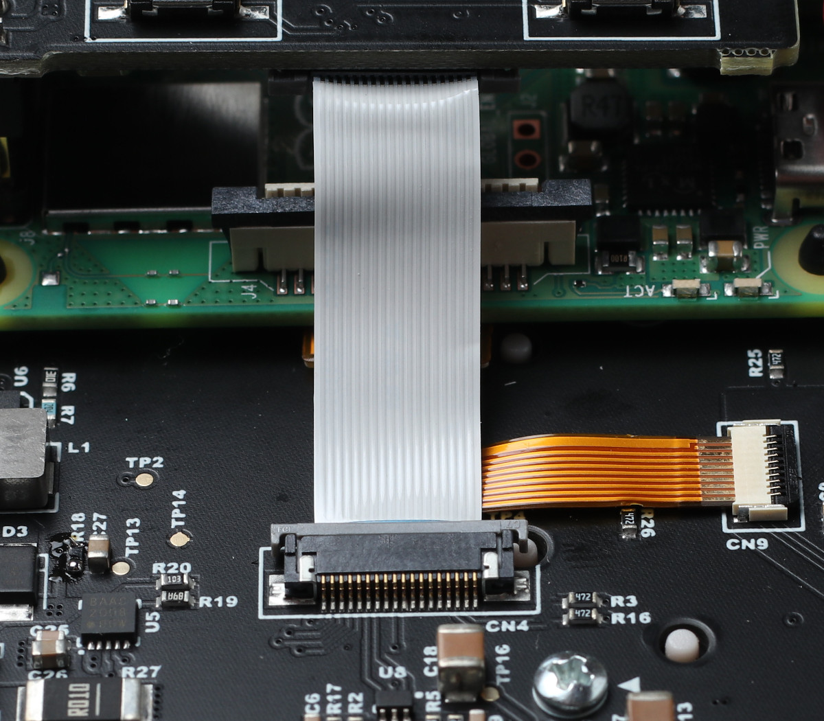
Figure 4: The white ribbon cable.
Control Board
The control board is the board attached to the front shell of the PiBoy. It contains the contacts for the buttons, the connector for the joystick, the controls for volume and screen brightness and the microcontroller that processes inputs and communicates with the Raspberry Pi. The microcontroller is what runs the PiBoy’s firmware.
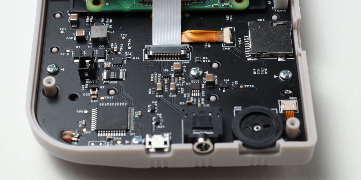
Figure 5: The control board in the lower half of the case.
Raspberry Pi Hat
The hat is the board mounted on top of the Raspberry Pi. It contains the connector for the screen cable and the white ribbon cable. It must be pushed fully down on to the GPIO pins of the Raspberry Pi.
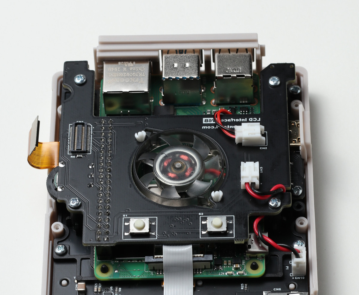
Figure 6: The Raspberry Pi hat board.
Screen Cable
The screen cable connects the LCD screen to the hat mounted on the Raspberry Pi. If this is not connected properly there will be no video output.
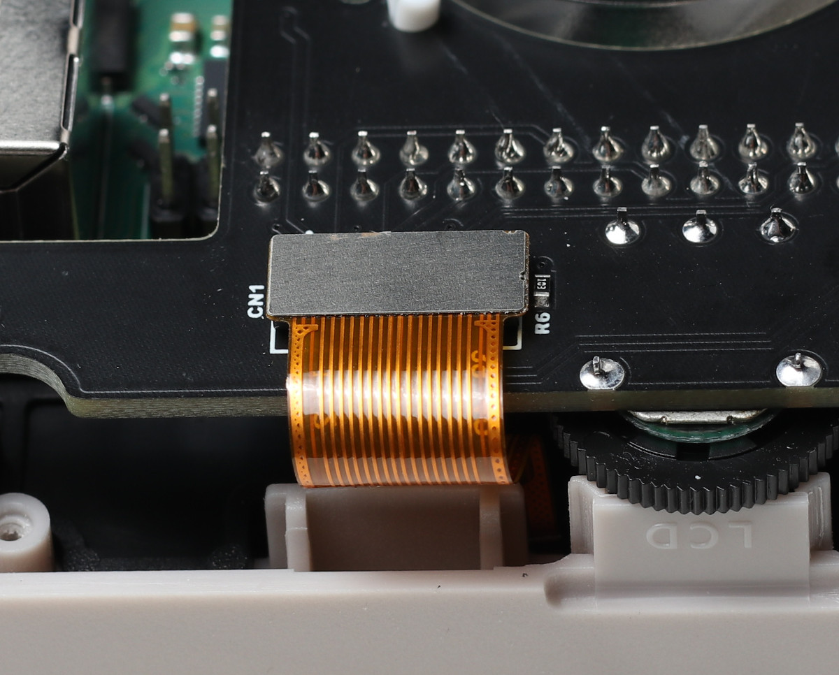
Figure 7: The screen cable.
Screen
The 640×480 IPS screen is held in place with a pair of plastic rails and sits behind the glass screen protector installed in the front half of the PiBoy’s shell.
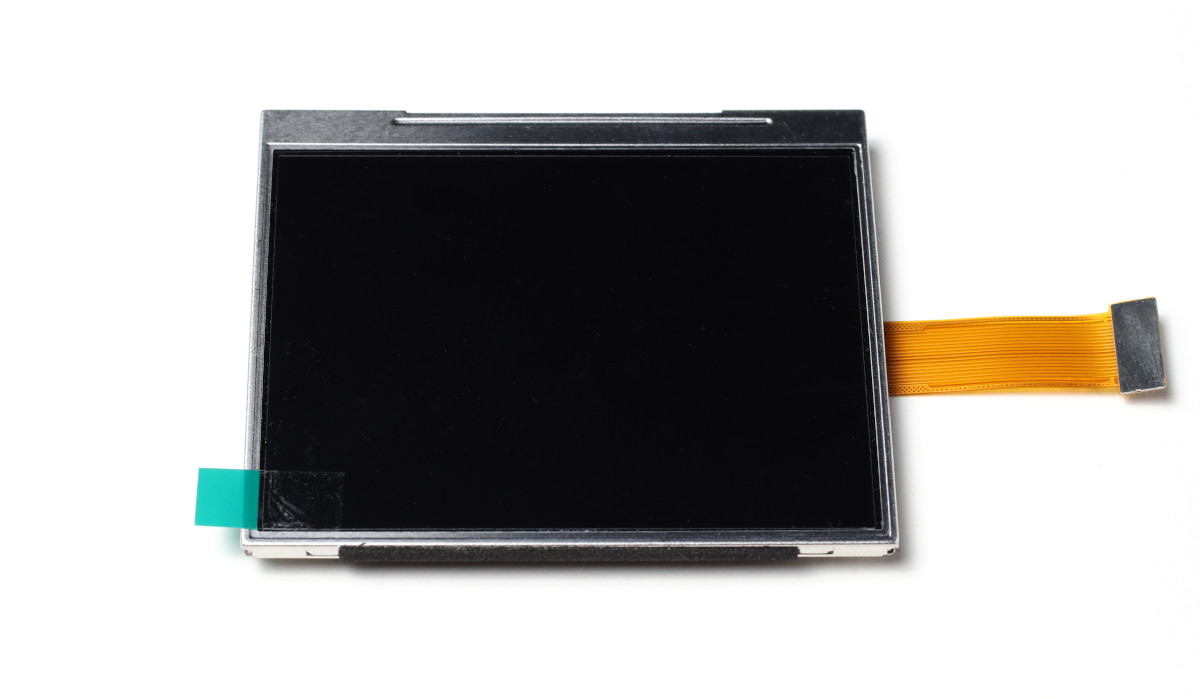
Figure 8: The LCD screen.
Fan
The fan is a 5VDC 10,000 RPM brushless fan. The fan connector is a 2 pin JST type. It is held in place with a pair of male and female plastic pins.
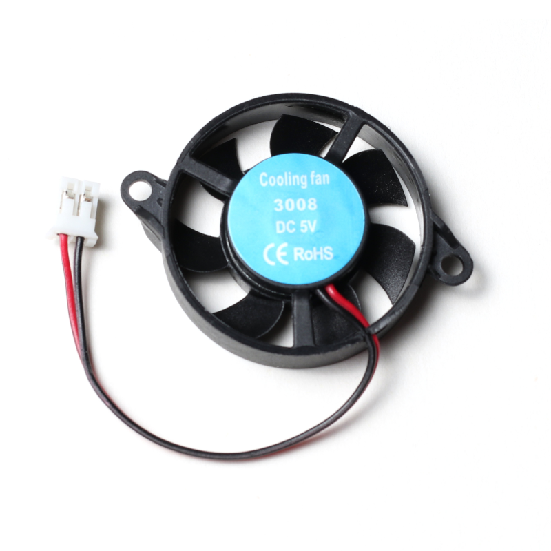
Figure 9: The PiBoy’s cooling fan.
Battery
The battery sits in the battery compartment of the back shell of the PiBoy. The battery is a single cell lithium polymer battery with a capacity of 4500 mAh. Typical run time with a completely charged battery for is about 4 hours.
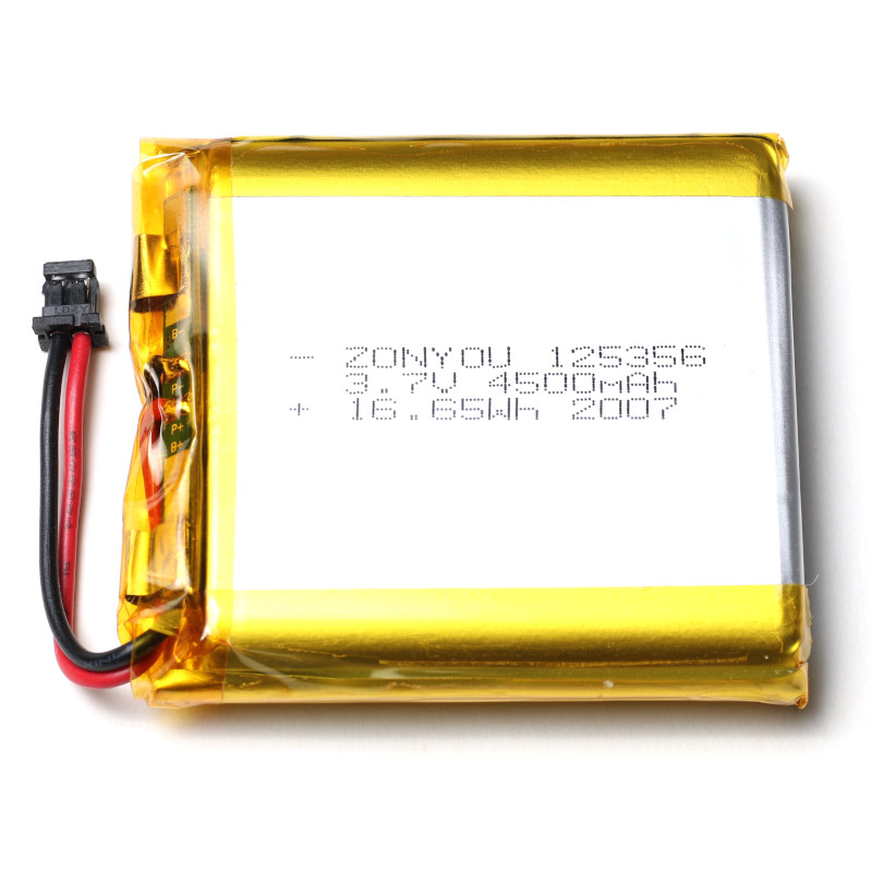
Figure 10: The PiBoy’s LiPO battery.
Article last updated on: 17 Jan 2022
