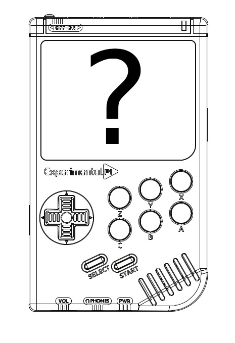
Figure 1: Troubleshooting problems with a PiBoy DMG build.
Solving Issues With a PiBoy DMG Build
This tutorial covers several problems you might encounter with a newly built PiBoy DMG kit and how to troubleshoot them. Potential sources of trouble are: the two ribbons cables inside the case, a low battery and an improperly flashed RetroPie image. It is always possible that the PiBoy hardware itself is damaged but it is the least likely source of a problem. If none of these troubleshooting steps solve your problem contact Experimental Pi’s support.
SD Card
One of the most common, if not the most common issue, you might encounter with a PiBoy DMG is an issue with your SD card. The primary issue with any SD card used in a PiBoy is it’s performance, we recommend that any card you use is rated class “A1” or better. Using a lower rated card will result in poor emulation performance and possibly problems running the operating system itself.
However, you need to be careful not to purchase counterfeit SD cards. Online sources of SD cards such as Amazon and eBay are full to the brim with counterfeit cards that usually are not what they promise to be, either in capacity or performance. We recommend buying your SD cards from physical/brick and mortar electronics stores; you are much more likely to receive genuine SD cards from these stores. You should also test the performance of any card you buy before using it in a PiBoy. See
this article to learn how to test the performance of an SD card.
Once you’ve verified the performance of the card you should proceed to flash either our official image or a stock RetroPie image. Be sure to decompress the image once you’ve downloaded it, the result of decompressing the downloaded image will an image file which is suitable for being burned to your SD card. If you burn the compressed image to the SD card the PiBoy will not boot. See
this article for details on flashing an operating system image to an SD card. If you do not flash the official image you’ll need to complete the final step of installing the custom Experimental Pi software after flashing a stock RetroPie image.
As a final note: the first boot after flashing an image will result in the PiBoy rebooting itself several times to complete it’s setup, this is normal and required for the image to complete it’s installation. Do not turn off the PiBoy before the boot cycling is completed.
SD Card Cable
One common source of problems is with either end of the gold SD card cable not being seated and latched properly. The end that goes in to the Raspberry Pi must be fully inserted. The end that goes in to the header on the board must be inserted fully, straight and fully latched. See the photos below for correct and incorrect examples.
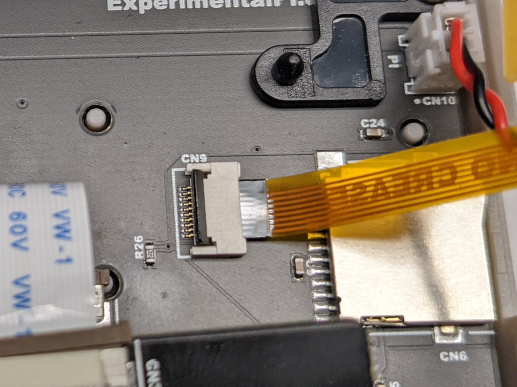
In figures 2 and 3 the gold colored SD cable is fully inserted in to the header, is inserted straight and the latch is fully latched. The cable is fully inserted when it stops at the back of the header. If the cable is crooked, the contacts on the cable will not make proper contact. If the latch is not full latched the contacts will not make contact.
Figure 2: The flipped style SD cable inserted in to the header properly and fully latched.
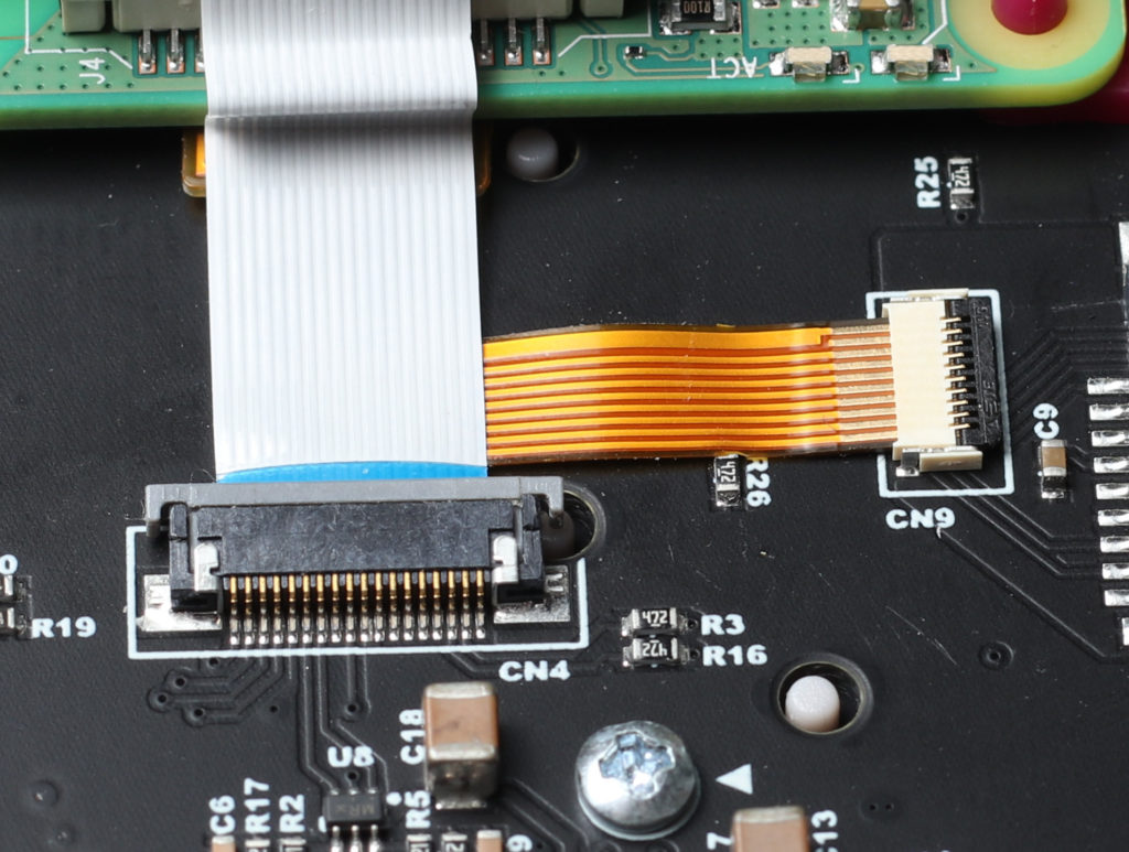
Figure 3: The flat style SD cable inserted in to the header properly and fully latched.
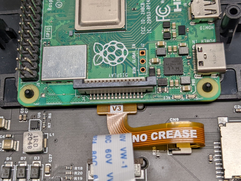
Figure 4 shows the Pi end of the gold SD cable full inserted in to the Raspberry Pi. The cable is fully inserted when it stops at the back of the header and will go in no further. The cable will also mostly lay flat when both ends are fully inserted in to their respective headers, with a small rise above the header where the ribbon flips over to be inserted in the control board.
Figure 4: The SD cable fully pushed in to the Raspberry Pi.
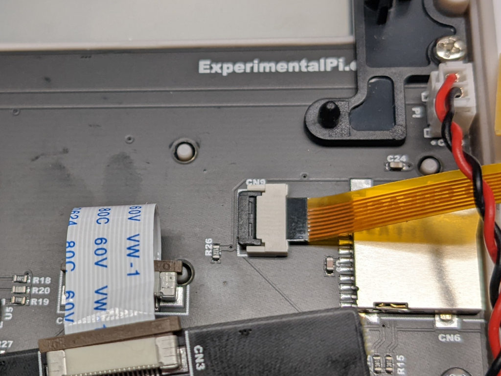
Figure 5 and 6 show the SD cable not fully inserted in to the header.
Figure 5: The flipped style SD cable not fully pushed in to the header.
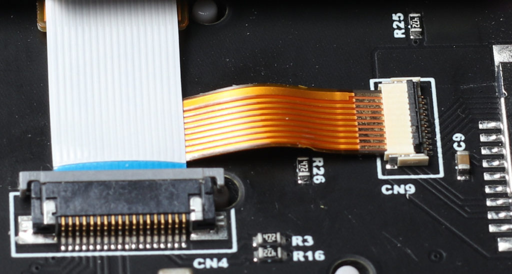
Figure 6: The flat style SD cable not fully pushed in to the header.
Figures 7 and 8 show the SD card header unlatched. When the latch is flipped up it is in the unlatched position. The latch must be pushed down all the way to ensure it’s fully latched. If the latch is not latched the contacts will not make contact and the SD card will not be read by the Raspberry Pi.
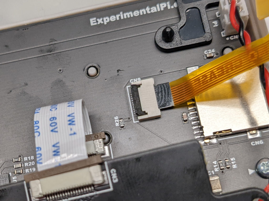
Figure 7: The flipped style SD cable header latch unlatched. The latch must be fully latched for proper operation.
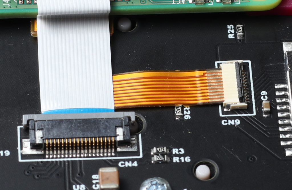
Figure 8: The flat style SD cable header latch unlatched. The latch must be fully latched for proper operation.
In figure 9 the Pi end of the gold SD cable is not fully inserted in to the Pi. Notice the the cable does not lay flat in this position. The cable must be pushed in until it stops at the back of the header. If a proper fit is not made the Pi will not be able to read the SD card.
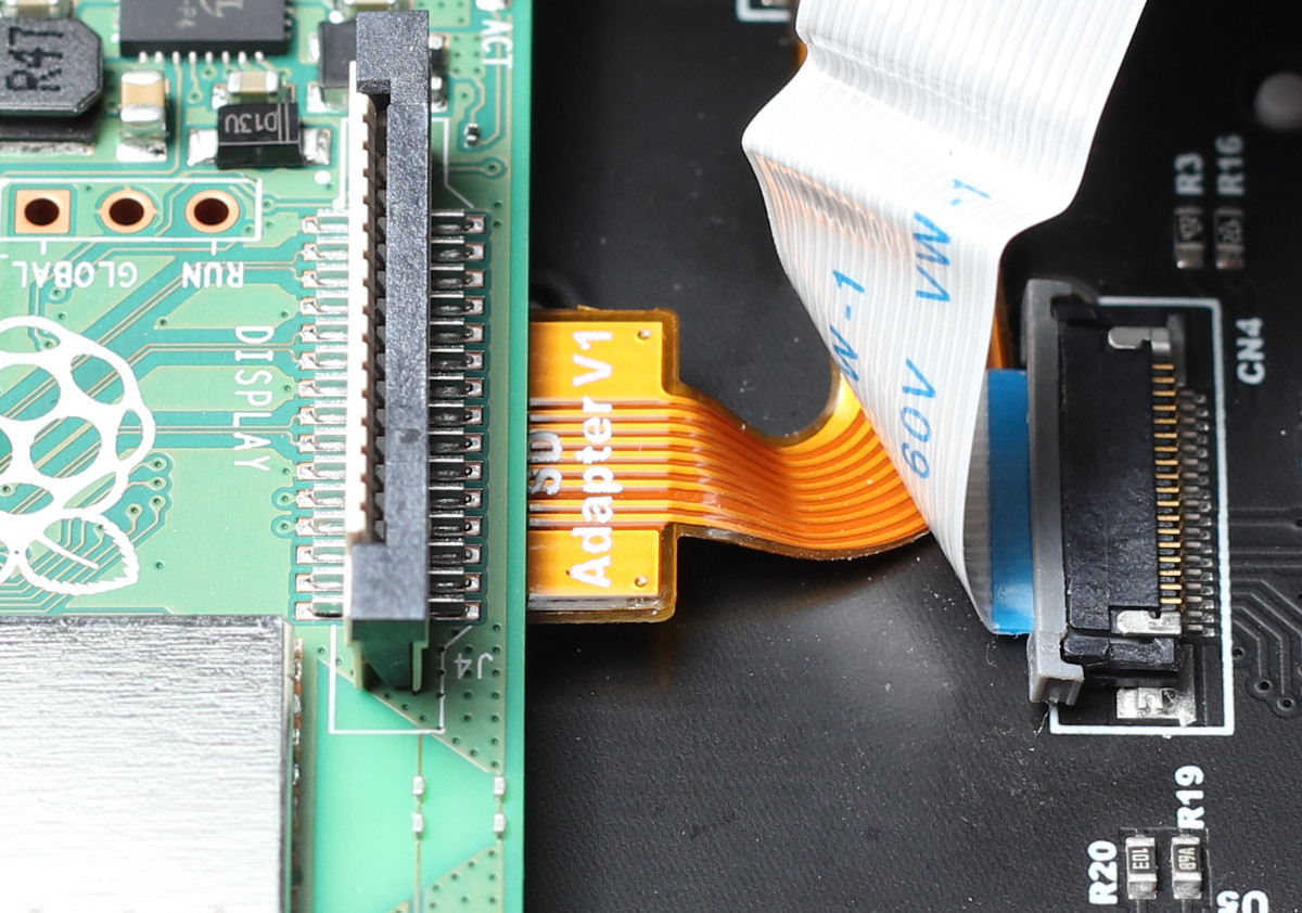
Figure 9: The SD card cable not fully pushed in to the Raspberry Pi.
Note that there are two types of SD cable. If you try to installed the flipped style cable on a board that uses the flat style, it will not work. Same if you try to install the flat style cable onto a board that uses the flipped style. If you are replacing the cable, it is recommended that you compare the original and the replacement to ensure you are using the correct cable.
White Ribbon Cable
The white ribbon cable is another common source of problems. The cable must be inserted in to the header fully, straight and latched. See the photos below for correct and incorrect examples.
Figure 10 shows the white ribbon cable correctly inserted in to its header and fully latched. This is how your cable and header should look for a correct installation. The cable is not inserted crooked and the latch is not loose or partially closed.
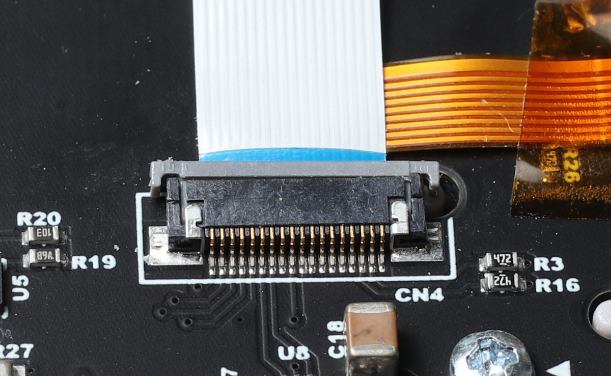
Figure 10: The white ribbon cable fully inserted and latched.
In figure 11 the white ribbon cable is not inserted straight in to the header. This will cause problems with proper operation of the PiBoy and may damage the white ribbon cable. Ensure that the white ribbon cable is inserted straight. The photo above shows a correctly inserted cable.
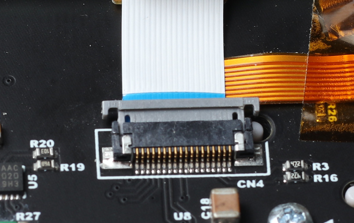
Figure 11: The white ribbon cable inserted crooked. If the cable is not inserted straight the PiBoy will not work properly.
Figure 12 shows the white ribbon cable’s header unlatched. If the latch is left unlatched the PiBoy will not operate properly. The first photo is this section shows the latch fully latched.
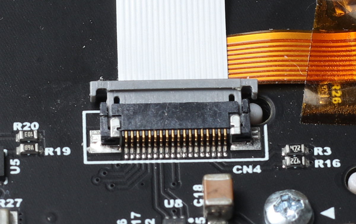
Figure 12: The white ribbon cable’s header unlatched. The latch must be fully closed for proper operation.
LCD Connector
The LCD connector must be pushed in until it clicks in to place and is flush with respect to the board. See the photos below for examples.
Figure 13 shows the LCD screen cable correctly attached and fully seated. When installing the connector it will snap in to place. If the connector does not sit flush with header it has not be attached correctly.
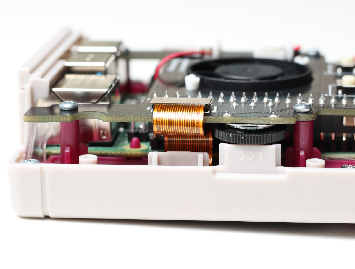
Figure 13: The LCD connector properly seated.
Figure 14 shows the LCD screen cable disconnected. The connected must be attached properly to the header for proper operation of the PiBoy.
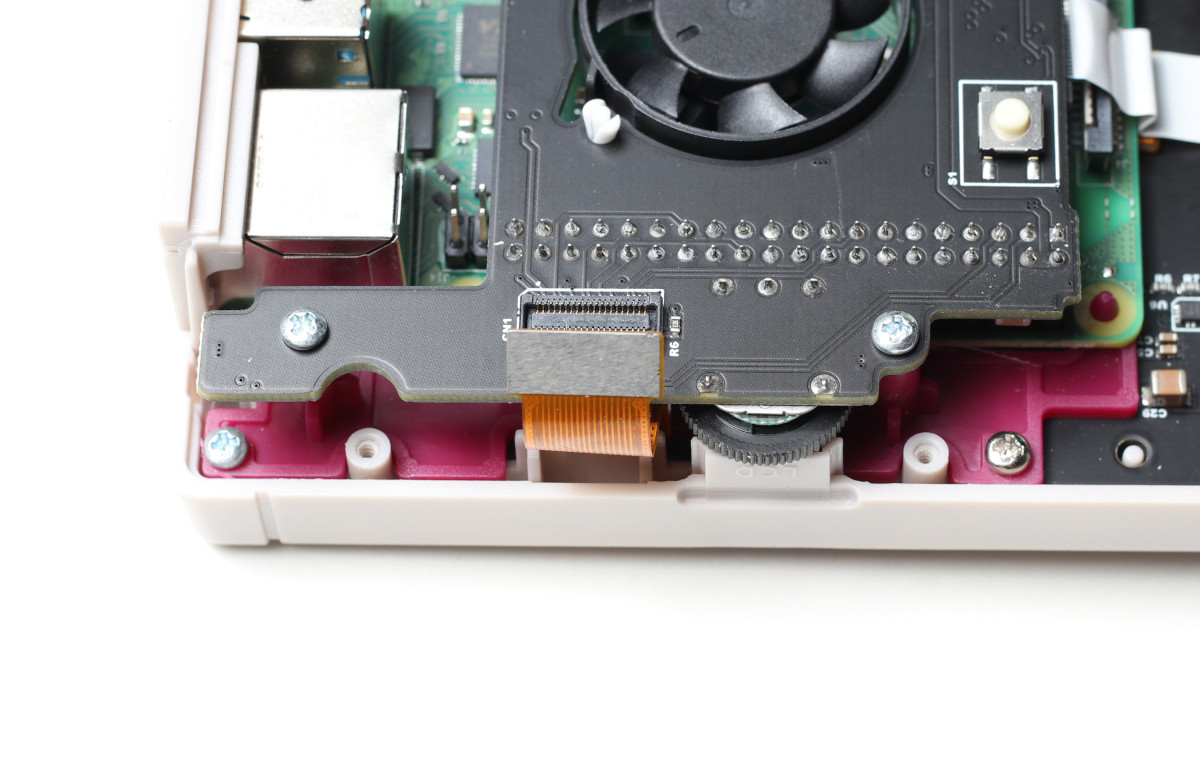
Figure 14: The LCD connector disconnected. The connector must be attached and seated for proper operation.
Hat Connection
The hat/fan board that sits on top of the Raspberry Pi must be fully pushed down on to the GPIO pins. If it is installed correctly the holes on the board will line up with the plastic risers and be flush with them. See the photos belows for correct and incorrect examples.
Figure 15 shows the hat board installed correctly on top of the Raspberry Pi. The hat has been fully pushed down on to the Pi’s header pins and the hat is flush with the plastic standoffs. If the hat is not fully pushed down you will not be able to install the screws to hold the board in place. Also, if the hat is not installed correctly the Pi may not be able to communicate with the hat and the case will not be able to be closed up properly once the back is installed.
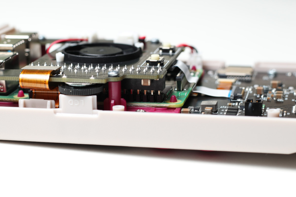
Figure 15: The hat fully and properly seated on the Raspberry Pi’s GPIO pins. Note that the board is also flush with the plastic risers.
Figure 16 shows the hat properly installed. Note that when the hat is properly installed the screw holes in the standoffs line up perfectly with the holes in the hat board. If these do not line up properly the hat has not been installed correctly.
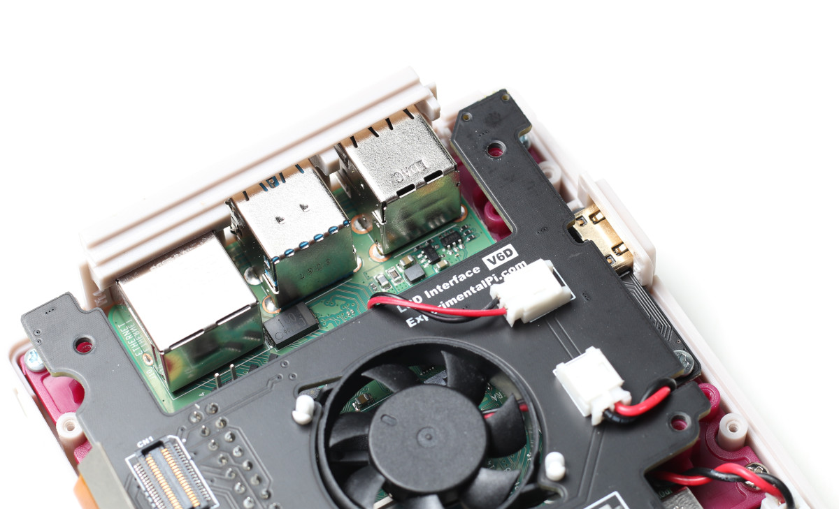
Figure 16: When installed correctly the holes in the hat line up with the plastic risers for installation of the screws.
Figure 17 shows the hat not fully pushed down on to the Pi’s header pins. When not fully pushed down the hat board is not flush with the plastic standoffs and the screws to hold the board in place cannot be installed.
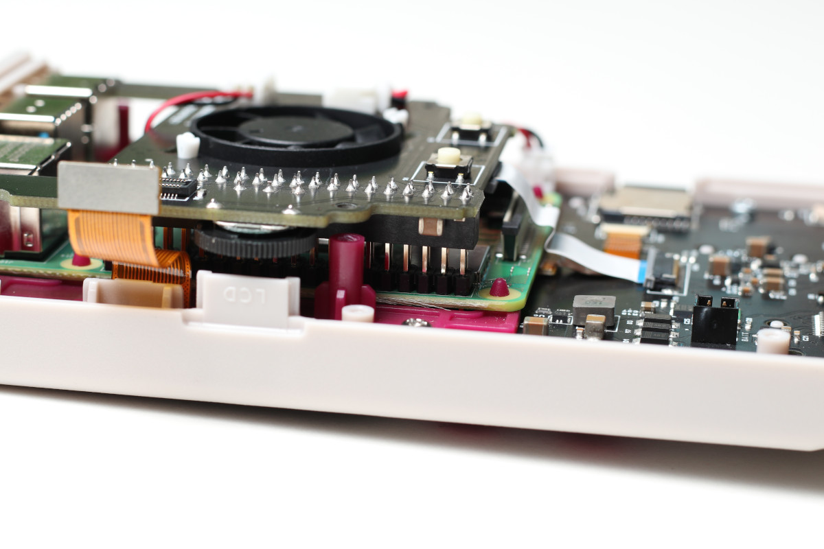
Figure 17: The hat not fully pushed down on to the GPIO pins.
Fan Board Wiring
All of the connectors on the fan board must be fully inserted and observe the proper polarity. The plastic connectors only go in one way due to the index mark on them. Do not force the connectors in backwards or damage will occur. See the photos below of a correct installation. Note the proper routing of the fan wiring.
Figure 18 shows all three of the fan connections on the hat board. A correctly installed fan will observe this exact wiring. Note the polarity of each connection. The fan connectors will only connect in one direction. Do not force the connectors in the wrong direction of they will be damaged.
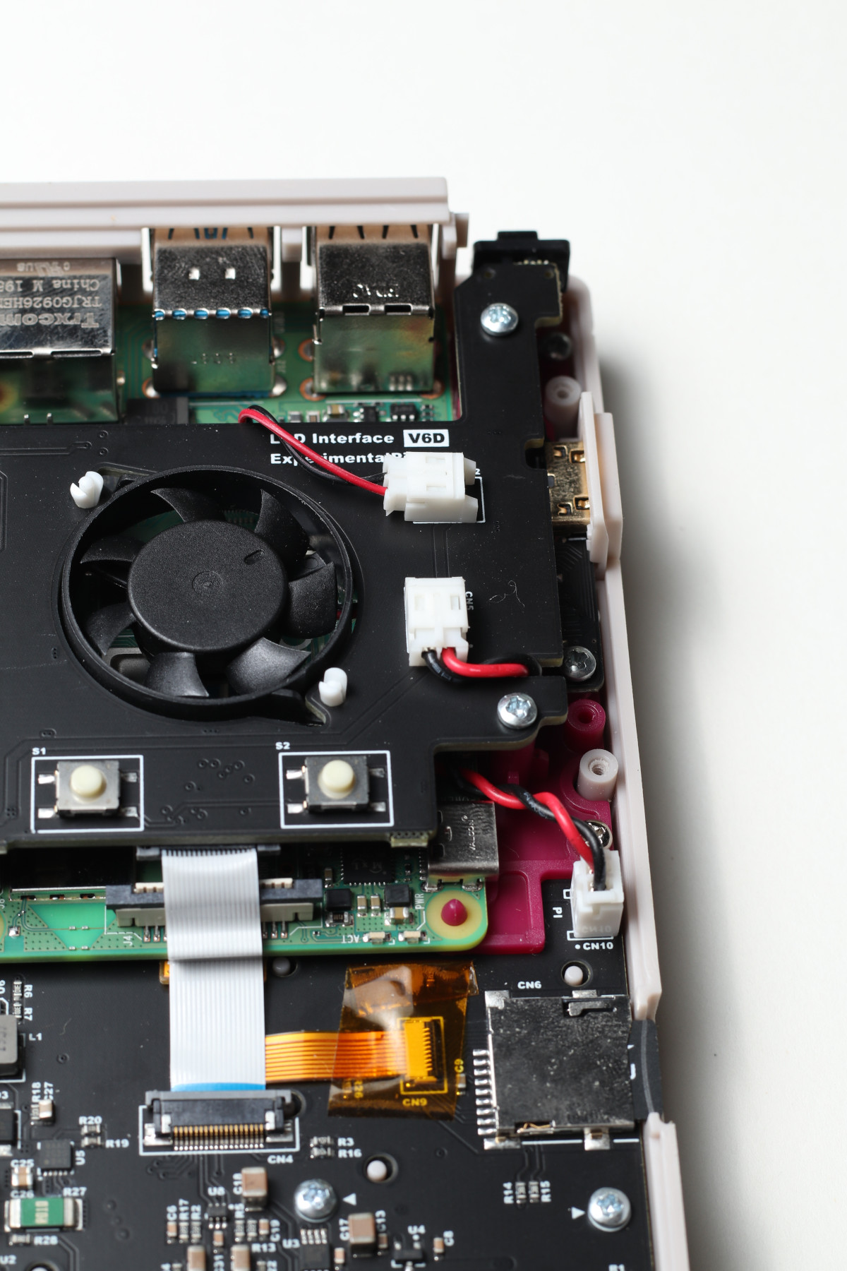
Figure 18: All of the connectors on the fan board connected properly. Follow this orientation for your PiBoy. The proper wiring routing is also shown.
Figure 19 shows how to correctly route the wire from the fan to the other side of the board. Do not route this wire in any other direction.
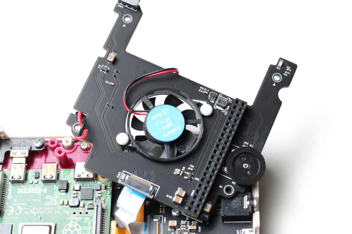
Figure 19: The proper routing of the fan wiring from the backside of the fan board.
After turning the PiBoy on the LCD screen is dark and the power light never comes on
- Check that that the battery is connected.
- Plug in the USB charger. The power light should light up even if that battery is not connected.
- If the power light is still not on check that the 18 pin ribbon cable in the case is connected.
- If the power light still does not come on, the PiBoy is damaged. Contact support.
After turning the PiBoy on the power light flashes green and then flashes red, finally the power light goes out
This means the PiBoy is not communicating with the Raspberry Pi.
- Make sure the micro SD card has been properly flashed with the software. See our tutorial for instructions.
- If the LCD screen still does not turn on check the following:
– LCD screen cable is correctly connected.
– 18 pin ribbon cable is correctly connected
– If both cables are correctly connected but the LCD screen still does not turn on, contact support.
- If the LCD screen comes on but displays garbage:
– Check that config.txt has not been modified.
– Check that the LCD screen cable is connected correctly.
– Check that the 18 pin ribbon cable is connected correctly.
– If none of the above problems are found contact support.
- If the LCD screen comes on and the text is legible note when the boot fails. If the boot process does not fail and Emulation Station launches there may be a battery voltage reading problem causing a false shutdown. If this is the case contact support.
- If booting fails before launching Emulation Station there may be a problem with the image. Re-image the SD card and try again. If booting still fails note where it failed and contact support.
Diagnosing issues with the help of the LEDs
Both the LED on the Pi hat(LCD/fan board) and the LEDs on the Raspberry Pi itself can provide helpful information for diagnosing issues.
In the below GIF, you can see how the LEDs on the Raspberry Pi should behave when you first start up the PiBoy DMG.
Figure 20: The Raspberry Pi on startup.
The green LED, on the left, will flash a few times before going off. Once the green light goes off, this means that it was able to read the SD card – this will rule out issues with the SD card slot or the SD card ribbon cable.
Afterwards, the red LED will turn off. Once the red LED is off, it means connection is established between the pi, hat, and main board, and that it was able to load the proper drivers.
Our software disables the LEDs on the Pi itself after booting up. Advanced users may want these lights to remain on for various reasons. To re-enable the LEDs, open the config.txt file from the boot directory on the SD card. There will be two sections labelled “Disable ACT LED” and “Disable PWR LED.” Each section will have two parameters. Simply comment out each line in each section by adding a # to the front of the line. This will prevent those settings from being used on startup.
If you power the PiBoy on with no SD card, the LED on the pi hat will blink red, from off to on. On older firmware, it may be green.
On shutdown, the same LED will flash on to off.
Once the PiBoy is talking to the pi, the LED will turn a solid color, this can be red, yellow, or green, depending on the battery and if it is charging. It will be green if it is done charging, or if it is running off of battery with 25% or more power. Once the battery gets down to 25%, the LED will change color as it loses power – first to yellow, then to another shade of yellow, and finally to red. The LED may also be red if the PiBoy is plugged in to charge, but has not completed charging.